Applications / Monocular depth
Passive long-range depth with one camera
A thin phase plate added to an existing camera or telescope encodes distance into every frame, and matched software reads it back. Nothing is emitted and no second camera is needed. The method has been demonstrated at distances of up to 5 km.
- Status
- Demonstrated outdoors with a telescope-based research system
- Range shown
- About 200 m to 5 km. Simulations show 10 km and more
- Added hardware
- One phase plate. No emitter and no second camera
- Paper
- Optics Express 30, 37925 (2022)
Why passive, why one camera
Most ways of measuring distance at range send out a signal. Lidar, time-of-flight cameras, structured light and gated imaging all carry an emitter, with its power, weight, eye-safety limits and cost, and they reach only as far as enough of their own light comes back.
Stereo is passive, but it needs two cameras held in calibration and a baseline that grows with the distance to be measured.
Encoding depth through a single aperture needs neither an emitter nor a baseline. The camera keeps its one optical path and uses the light the scene already provides (Fig. 1).
Range is not the whole comparison. Active sensors measure distance directly and more precisely. What depth encoding offers is distance from a camera alone, at ranges where the other passive option stops.
What you add to an existing camera
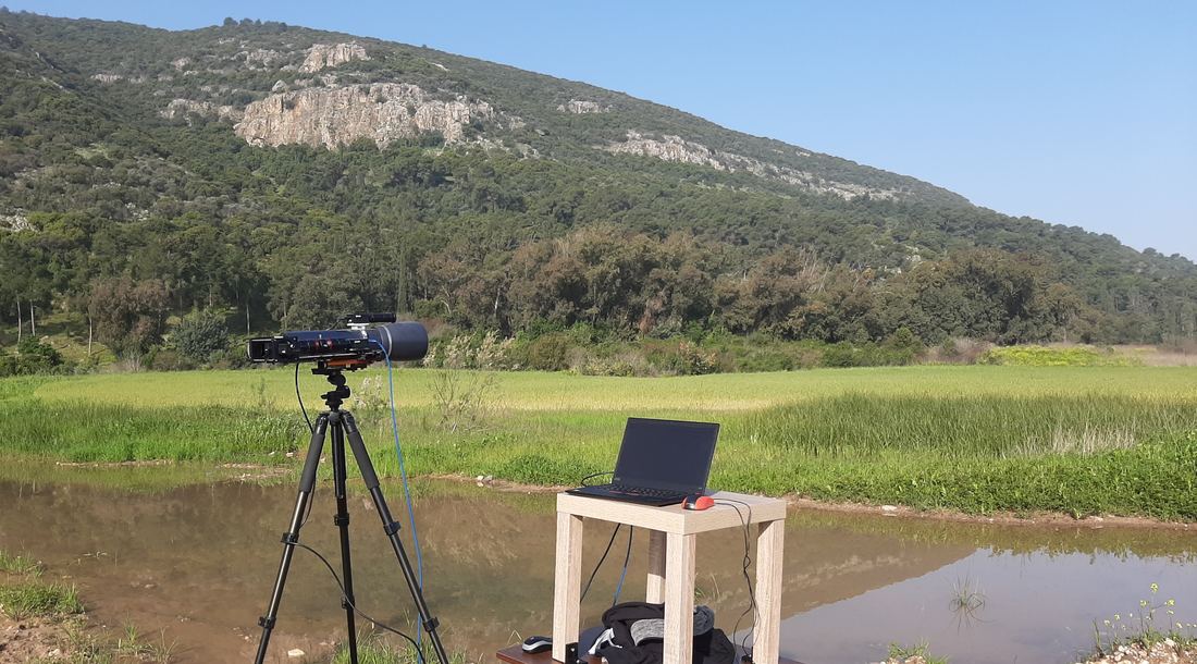
The added hardware is a phase plate at an aperture plane of the optics: in front of the lens or telescope, or inside the instrument. The plate is thin, light and passive, and needs no power. The published demonstrator reached that plane with a lens relay behind a small telescope (Fig. 2).
We design the plate for the instrument: its aperture and focal length, its waveband, and the range of distances that matters. A plate can be designed for the camera’s band, from the visible to the mid-wave infrared. For large apertures the plate is large too, and we cast it by near-index matching, up to the size of a telescope aperture.
How distance is read from the image
The plate used in the published work gives the optics a double-helix response: every point of light reaches the sensor as two spots, and the line joining them turns as the point’s distance changes (Fig. 3). The turn is fastest at short range and slows with distance, which is why precision is best close in. A plate designed for another instrument and range may encode distance differently.
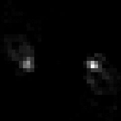
240 m
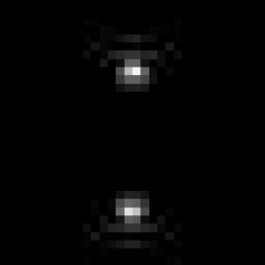
473 m
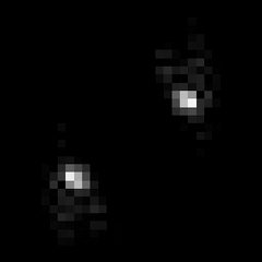
1.1 km
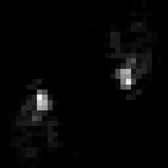
2.1 km
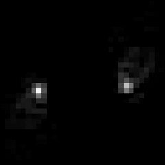
5.5 km
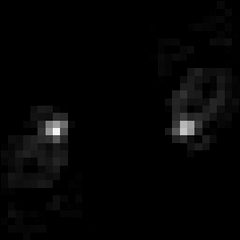
10 km
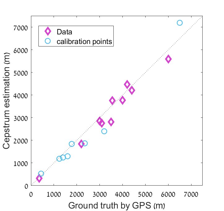
A natural scene is not made of points, but each small region of it behaves the same way: it appears as two copies of itself, shifted along that line. The software finds the direction of the shift, either from the region’s cepstrum, a transform in which a repeated pattern shows up as a pair of peaks, or with a neural network. A calibration recorded once for the instrument turns the angle into a distance (Fig. 4).
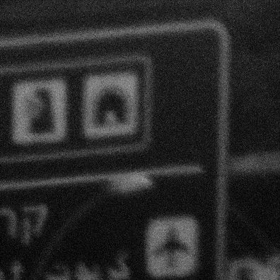
Without the plate
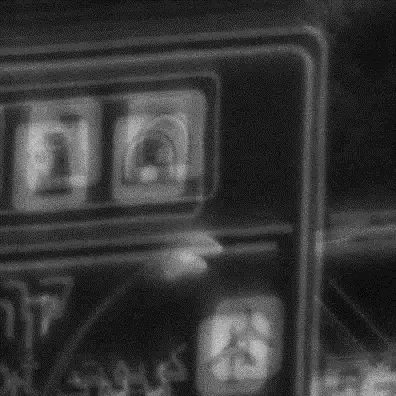
Through the plate: every feature appears twice
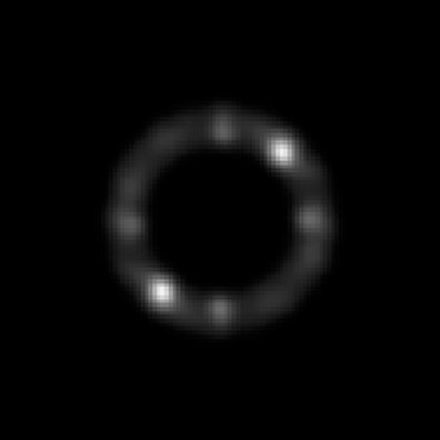
Its cepstrum: the bright pair marks the direction of the shift
What has been shown
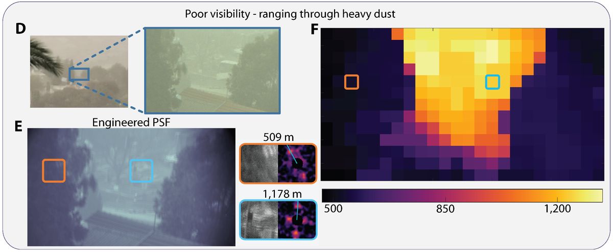
The published system was tested outdoors on moving targets, on static scenes with varied textures and in poor visibility, at distances beyond 1.7 km.1 Later measurements with the same approach reach 5 km.
| Scene | Distances | Shown in |
|---|---|---|
| Car driving away | 200 to 800 m | Fig. 5 |
| Small drone flying away | About 380 m to 1.1 km | Fig. 5 |
| Truck on a dusty road | About 300 to 700 m | Fig. 5 |
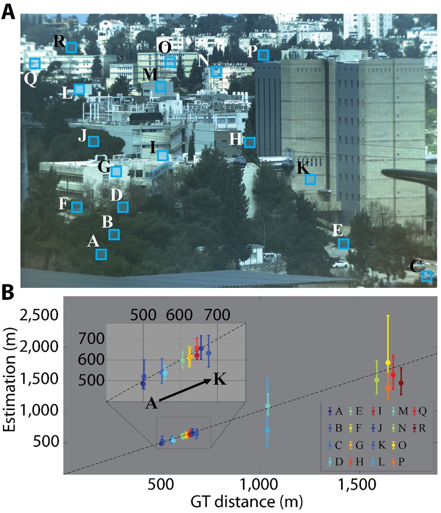
| City scene, 18 regions | 500 m to 1.7 km | Fig. 6a |
| City scene with GPS reference | About 350 m to 6 km | Fig. 6b |
| Scene in heavy dust | 500 m to 1.2 km | Fig. 7 |
The car sequence and Figs. 6a and 7 are from the 2022 paper.1 The other measurements are from the group’s presentations.
A car drives away from the telescope, from about 200 m to 800 m. The white box marks the region being ranged; the two small panels show that region and its cepstrum with the detected direction. The plot adds one estimate per frame, by peak location (blue) and by neural network (green), on the reference distance (dashed).
A small drone flies away from the camera, from 377 m to about 1.1 km. The plate doubles its image, and the angle between the two copies changes with the distance, which is shown above the frame.
A truck drives away on a dusty road. The passive estimate (blue) follows it throughout. The laser rangefinder (red) agrees when it gets a return from the truck, and otherwise reads about 40 m or gives no reading.
What limits it
- Precision is a fraction of the distance, and it loosens with range. Air turbulence is the main source of error far out: in the published system, 10% precision held to about 1.5 km in calm air and to about 500 m in strong turbulence.1
- The region being ranged needs texture. Uniform surfaces are hard, and so are regions dominated by straight horizontal or vertical lines.
- Aperture and field of view trade against precision. A larger aperture gives stronger depth cues; a wider field of view gives weaker ones.
- The plate slightly lowers the sharpness of the ordinary image.
- Results so far range selected objects and regions. A distance for every pixel, together with the restored sharp image, is the development step of a full project.
- Computing load grows with the frame rate and with the number of regions ranged.
Where it helps
Passive single-camera ranging matters most where an emitter is unwelcome or too heavy, and where the distances are too long for stereo.
- Long-range observation and site monitoring: distance to what a camera already sees, at hundreds of meters to kilometers.
- Detecting and tracking small drones and other objects in the air.
- Drones and ground robots, where the weight and power of a lidar are hard to carry.
- Navigation and landing aids.
- Surveying and mapping from a single camera.
Working with us
We are looking for integration partners who want to add passive depth to an imaging system they already build or operate.
A project starts from your optics and your range requirement. We design a plate for them, make it, demonstrate ranging on agreed targets with your system, and then extend the software toward a full depth image.
Reference
- N. Opatovski, D. Xiao, G. Harari and Y. Shechtman, “Monocular kilometer-scale passive ranging by point-spread function engineering,” Optics Express 30, 37925 (2022).